
I wanted to create this thread to share what I learned when trying to retrofit the HUD and 360. There is a lot of useful video showing how to take apart the dashboard, where screws are located, where stowed connectors are located.
I initially started this project thinking that the connector I saw up in the dash HUD area was the actual connector for the HUD. ( I shoved my smaller phone up from the bottom in hopes of seeing anything) Since the car was so new, there isn't much information out there as to what can be added. For example, we know that we can add in Remote Start which comprises of some new Key Fobs and a Black Box unit ( receiver) that is placed in the rear upper headliner location. So we kind of know that Honda/Acura put provisional wiring and connectors for items that are "easy to retrofit". In my mind, I thought they had their $hit together and would make it easy for someone to add in items. The reason I thought this was because most of the areas where units belonged, had a capped/stowed connector tied to the harness with either black electrical tape or orange tape. Sometimes some manufacturers use a bright color like yellow or orange to indicate locations to mount harnesses as a reference during the production line. In this case, the orange is used at some connector locations that are stowed but have an open connector. I have not yet scoured information on those yet ,but i am thinking they are for possible lighting additions.
Yet in other locations, the black tape is used and wraps up the entire connectors, pressing them against the main harness. In the location of the 360 degree unit, the connector actually has a cap that is removable which is shown in the video. I assumed it was the same for the "HUD connector".
I decided at that point, to go ahead and order the parts so that i would have them to test fit, connect. The parts came and I saw there were two connectors on the HUD so I began looking for more than 1 connector. Since I had no idea of what the unit was connected to , meaning a high level block diagram, I could only assume that the main harness had two connectors tucked away nearby. I also had no idea what type of information was being sent via Canbus from or to whatever unit. I figured if the HUD was presenting/displaying navigation information, then it was already in the TECH/ASPEC coming from the navigational unit somewhere in the dash. I was wrong. I learned that the signal for HUD_UART was coming from the cluster, not from existing connectors on TECH/ASPEC but instead from a blanked-off area of the cluster where the ADVANCED cluster had outputs going to the HUD.
I also learned that during the purchase of the parts that the HUD multivisor switch was not individual HUD switches but instead a whole unit of switches together. There was no cheap alternative to buying a button and popping it in.
I didn't want to give up, so i spent many hours thinking about how i could just tap into the signals needed, such as power from a fuse, ignition ON signal, and create my own harness to connect to what i needed. But that was put to rest once I realized the cluster was different. Used price I saw was around 1300. If it was $200, i might have ordered and continued. The only thing I still do not know are the part numbers for the connectors and wiring needed. There are no markings on the connectors to tell you its A1, B1,C1 or if it was something like P200 or J240. So even if i knew i needed an "LVDS connector" I don't have or know of any document telling me what to order such as a honda part number 78200-TYA-A0X . As for the HUD connector, I don't have that part number either. I probably could open it see a connector PN designation on it and order the mating connector from a place like Tyco electronics online.
Now switching gears here, the 360 camera might be more doable, since i believe that the capped connector is there on the right side floorboard. BUT i could be making a mistake on that as well. I was unable to find the 4 coax connections stowed away. I would need to see where they were routed on an ADVANCED model to follow the routing path / connection points. I would also need to know the part marking to order the 4. I would assume that two mirrors and a front grill camera were needed. The reason why i think this would work is because it interfaces with the screen and the plug is empty waiting for that signal input. I am actually kind of disappointed that they didn't use a USB or RCA style input on the screen that could be retrofitted with aftermarket solutions. There are only connections on each unit for exactly what it was designed for. ( well except the cluster because its missing what i need !)
I will post the images of what i found for each unit as much as i can to help the community figure out possible aftermarket solutions to interfacing with the head unit. On ebay or amazon, they have new head units for BMW models that work well with Android and offer more inputs to add items like cameras and so on.
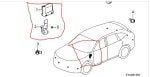
IMAGE: Orange electrical taped connectors .
![Image]()
IMAGE: Black electrical taped connectors or junctions
![Image]()
IMAGE: HUD unit connectors
![Image]()
IMAGE: Headunit Display
![Image]()
IMAGE:
360 SURROUND unit with 4 connectors for cameras,
F(5P), E (5P), D (5P), C (5P), LVDS B (3P), and main A (24P)
![Image]()
ADVANCED cluster with LVDS on the left (C1) and main HUDUART in the middle (B1).
![Image]()
ASPEC CLUSTER missing connectors which are on the ADV.
![Image]()
High Level Block diagram showing connections
![Image]()
Cluster wiring shows that even though it is a 20 pin connector, there are only 2 signals coming out for HUDUART, and the 3 pin connector is for the LVDS. So completely designated for HUD usage.
![Image]()
Thats all i am going to write for now. I will add other images later. I have been dreading really editing and making a video because i didn't want to post a "failure" but I figured there could be more people willing to try to connect or go further to make it happen. I also rendered the video multiple times and had it copy-righted due to music playing in the background. So after the 3rd time of fixing and uploading to youtube, I almost just said F-it and not post. But it uploaded with no copy right strikes.
I initially started this project thinking that the connector I saw up in the dash HUD area was the actual connector for the HUD. ( I shoved my smaller phone up from the bottom in hopes of seeing anything) Since the car was so new, there isn't much information out there as to what can be added. For example, we know that we can add in Remote Start which comprises of some new Key Fobs and a Black Box unit ( receiver) that is placed in the rear upper headliner location. So we kind of know that Honda/Acura put provisional wiring and connectors for items that are "easy to retrofit". In my mind, I thought they had their $hit together and would make it easy for someone to add in items. The reason I thought this was because most of the areas where units belonged, had a capped/stowed connector tied to the harness with either black electrical tape or orange tape. Sometimes some manufacturers use a bright color like yellow or orange to indicate locations to mount harnesses as a reference during the production line. In this case, the orange is used at some connector locations that are stowed but have an open connector. I have not yet scoured information on those yet ,but i am thinking they are for possible lighting additions.
Yet in other locations, the black tape is used and wraps up the entire connectors, pressing them against the main harness. In the location of the 360 degree unit, the connector actually has a cap that is removable which is shown in the video. I assumed it was the same for the "HUD connector".
I decided at that point, to go ahead and order the parts so that i would have them to test fit, connect. The parts came and I saw there were two connectors on the HUD so I began looking for more than 1 connector. Since I had no idea of what the unit was connected to , meaning a high level block diagram, I could only assume that the main harness had two connectors tucked away nearby. I also had no idea what type of information was being sent via Canbus from or to whatever unit. I figured if the HUD was presenting/displaying navigation information, then it was already in the TECH/ASPEC coming from the navigational unit somewhere in the dash. I was wrong. I learned that the signal for HUD_UART was coming from the cluster, not from existing connectors on TECH/ASPEC but instead from a blanked-off area of the cluster where the ADVANCED cluster had outputs going to the HUD.
I also learned that during the purchase of the parts that the HUD multivisor switch was not individual HUD switches but instead a whole unit of switches together. There was no cheap alternative to buying a button and popping it in.
I didn't want to give up, so i spent many hours thinking about how i could just tap into the signals needed, such as power from a fuse, ignition ON signal, and create my own harness to connect to what i needed. But that was put to rest once I realized the cluster was different. Used price I saw was around 1300. If it was $200, i might have ordered and continued. The only thing I still do not know are the part numbers for the connectors and wiring needed. There are no markings on the connectors to tell you its A1, B1,C1 or if it was something like P200 or J240. So even if i knew i needed an "LVDS connector" I don't have or know of any document telling me what to order such as a honda part number 78200-TYA-A0X . As for the HUD connector, I don't have that part number either. I probably could open it see a connector PN designation on it and order the mating connector from a place like Tyco electronics online.
Now switching gears here, the 360 camera might be more doable, since i believe that the capped connector is there on the right side floorboard. BUT i could be making a mistake on that as well. I was unable to find the 4 coax connections stowed away. I would need to see where they were routed on an ADVANCED model to follow the routing path / connection points. I would also need to know the part marking to order the 4. I would assume that two mirrors and a front grill camera were needed. The reason why i think this would work is because it interfaces with the screen and the plug is empty waiting for that signal input. I am actually kind of disappointed that they didn't use a USB or RCA style input on the screen that could be retrofitted with aftermarket solutions. There are only connections on each unit for exactly what it was designed for. ( well except the cluster because its missing what i need !)
I will post the images of what i found for each unit as much as i can to help the community figure out possible aftermarket solutions to interfacing with the head unit. On ebay or amazon, they have new head units for BMW models that work well with Android and offer more inputs to add items like cameras and so on.
IMAGE: Orange electrical taped connectors .
IMAGE: Black electrical taped connectors or junctions
IMAGE: HUD unit connectors
IMAGE: Headunit Display
IMAGE:
360 SURROUND unit with 4 connectors for cameras,
F(5P), E (5P), D (5P), C (5P), LVDS B (3P), and main A (24P)
ADVANCED cluster with LVDS on the left (C1) and main HUDUART in the middle (B1).
ASPEC CLUSTER missing connectors which are on the ADV.
High Level Block diagram showing connections
Cluster wiring shows that even though it is a 20 pin connector, there are only 2 signals coming out for HUDUART, and the 3 pin connector is for the LVDS. So completely designated for HUD usage.
Thats all i am going to write for now. I will add other images later. I have been dreading really editing and making a video because i didn't want to post a "failure" but I figured there could be more people willing to try to connect or go further to make it happen. I also rendered the video multiple times and had it copy-righted due to music playing in the background. So after the 3rd time of fixing and uploading to youtube, I almost just said F-it and not post. But it uploaded with no copy right strikes.